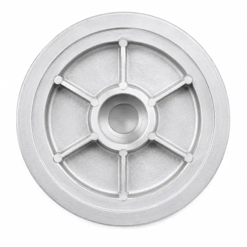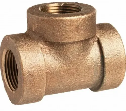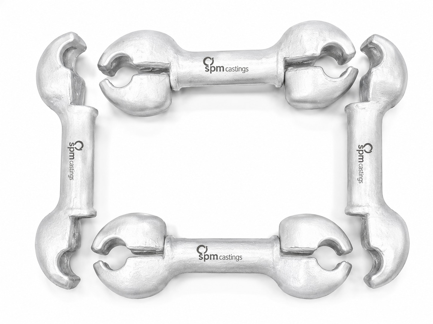
A spacer that looks reusable can still have a burr, distorted face, enlarged bore, or incorrect position that changes bearing preload, gear mesh, seal compression, or shaft alignment. You will be able to identify the part, inspect and measure it, confirm the assembled stack, reinstall it correctly, and verify the controlled dimension after testing.
Key takeaways
- Identify whether the spacer controls distance, preload, endplay, position, or clamp load.
- Clean mating faces and inspect for burrs, cracks, fretting, corrosion, and distortion.
- Recalculate the complete assembly stack instead of matching the removed spacer alone.
- Record test results and set the next inspection point before returning equipment to service.
Identify the Spacer’s Function Before You Remove or Reuse It
A removed spacer is not automatically the correct replacement. Identify what it controls before measuring or reusing it: fixed shaft distance, bearing preload or endplay, gear or pump position, or a crush-controlled clamp load. Spacers after oil engine repairs must match the engine or equipment service specification, not merely the removed part’s nominal length.
| Type | Function | Specification to verify |
|---|---|---|
| Fixed-distance sleeve | Sets a shaft, bearing, or component position | Installed length, bore, outside diameter, material, and shoulder clearance |
| Axial bearing spacer | Controls bearing preload or endplay | Thickness, parallelism, hardness, and the specified endplay or preload |
| Shim | Adjusts gear, pump, or shaft location | Thickness range, stack order, flatness, and resulting backlash or alignment |
| Crush spacer | Establishes clamp load as it deforms | New-part requirement, crush height, material, and tightening procedure |
Use the service manual, assembly drawing, or repair measurement record to select the specification. A chamfer or radius can clear a shaft shoulder or fillet; reversing it can damage a seal lip or prevent seating. Compare the bore and outside diameter with the adjacent shoulder and seal before applying force.
- Mark the original orientation only as a reference; confirm it against the drawing.
- Reject gasket material, sealant, random washers, and extra shims as substitutes. They can relax, migrate into an oil passage, or change clamp load.
- Record installed thickness, material and temper or hardness, surface finish, flatness, bore, outside diameter, and the measuring instrument. These records make spacers for oil engines traceable when stack-up or material—not nominal length—causes the failure.
Clean and Inspect Every Surface Before Installation
Treat spacers for equipment repairs as precision parts, not generic washers. Clean both faces, the bore, shoulders, locating pilots, bolt holes, threads, oil passages, sealing lands, and adjacent contact areas with an approved solvent; dry them with lint-free cloth and compressed air filtered for water and oil.
- Look for raised burrs, dents, galling, fretting scars, embedded debris, rust, coolant residue, and water-trapping crevices.
- Check chamfers and radii against the shaft shoulder, housing fillet, and seal. A reversed chamfer can prevent seating or cut a seal lip.
- Confirm that each oil passage is open and that contact marks are even rather than concentrated on one edge.
- Inspect aluminium or brass against steel for galvanic or crevice corrosion, especially where wash fluid or condensation can displace oil.
- Record the installed thickness, material and specified temper or hardness, surface finish, flatness, bore, outside diameter, and inspection instrument. A nominal drawing size cannot reveal face distortion or stack-up.
Damage that changes seating, alignment, sealing, oil flow, or load distribution requires replacement:
| Condition | Decision | Reason |
|---|---|---|
| Crack, warped face, deep score, or heavy galling | Replace | Load and stack height become unpredictable |
| Fretting, pitting, or corrosion at a contact surface | Replace | The joint can settle or lose preload |
| Blocked passage, damaged thread, lost locating step, or oversize bore | Replace | Oil flow or location is no longer controlled |
| Light burr only | Deburr and reinspect | Remove no material that changes thickness or chamfer geometry |
Measure the Spacer and Recalculate the Assembly Stack
Verify the spacer against the equipment service specification, then recalculate every dimension it controls; the removed part is evidence, not authority. A fixed-distance sleeve and an axial bearing spacer do not control the same result, while a shim changes gear, pump, or shaft position. A crush spacer requires its specified installed height.
Use clean, lint-free contact faces and calibrated instruments. Record these checks:
- Measure thickness at several points with a micrometer. Compare the readings for parallelism, then calculate the installed stack from every spacer, shim, gasket, shoulder, and bearing dimension.
- Check bore and outside diameter with a bore gauge or vernier caliper. Confirm that the spacer fits its pilot without binding or excessive radial movement.
- Place the part on a surface plate and check flatness with a dial indicator or straightedge. A distorted face creates uneven loading even when the average thickness is correct.
- Record the measured installed thickness, material, temper or hardness, surface finish, and inspection instrument. Nominal drawing size alone will not reveal stack-up or face distortion.
Confirm the controlled clearance after assembly. Compare shaft endplay or runout with the equipment limit for rotating assemblies, check gear backlash for gear trains, and verify leak-free seal seating for sealing joints.
An oil-pressure or leak check alone cannot prove correct spacer position; pressure can exist while a mispositioned spacer damages a bearing, gear, or seal. These records make spacers after oil engine repairs traceable and prevent incorrect reuse of spacers for oil engines.
Reinstall the Spacer in the Correct Orientation and Load Sequence
A spacer installed upside down can cut a seal, block an oil feed, or turn correct bearing preload into excessive endplay. Before applying force, match its type—fixed-distance sleeve, axial bearing spacer, shim, or crush spacer—to the equipment service specification; these parts are not interchangeable.
1. Align the spacer’s bore, outside diameter, locating step, chamfer, and oil holes with the adjacent shaft shoulder, housing, seal, and passage. Put the chamfer against the shaft fillet or seal side only where the service drawing specifies it.
2. Place the spacer against clean, dry, fully seated faces. Do not substitute a gasket, sealant, random washer, or extra shim; each can compress, migrate, block oil, or change clamp load.
3. Rebuild the stack in the specified order, including bearings, gears, seals, washers, and shims. Keep any marked oil-passage position unchanged and prevent the spacer from rotating while the assembly closes.
4. Tighten fasteners in the service-manual sequence, usually in gradual cross-pattern stages, using the specified torque or torque-angle value. Do not use bolt tightening to force a warped spacer or incorrect stack into position.
5. Measure the controlled result before closing the housing: shaft endplay or runout, gear backlash, bearing preload, or seal seating. A leak-free joint and normal oil pressure cannot prove correct spacer alignment.
For spacers for equipment repairs, record the installed thickness, material and hardness, face condition, and oil-hole position. Aluminium parts also need checks for compression marks, edge peening, bore growth, and permanent thickness loss; replace one that has embedded or flattened under clamping.
Test, Record, and Set the Next Inspection Point
After reassembly, measure the controlled result, not just oil pressure. Check shaft endplay and runout for rotating assemblies, gear backlash for gear trains, and leak-free seal seating at sealing joints; compare each reading with the equipment service limit. A pump can produce pressure while a misplaced spacer still damages a bearing, gear, or seal.
| Spacer type | Measurement it controls | Replacement evidence |
|---|---|---|
| Fixed-distance sleeve | Installed length, parallelism, bore, and outside diameter | Drawing or service-manual dimension, material, and finish |
| Axial bearing spacer | Shaft endplay or bearing preload | Manufacturer’s endplay or preload limit and measured stack |
| Shim | Gear, pump, or shaft position; often backlash or runout | Thickness, position, and resulting backlash or runout |
| Crush spacer | Final compressed height and bearing preload | Specified crush range and a new-part requirement |
For spacers after oil engine repairs, choose the part from the equipment specification, not from the removed part alone. Record:
- Installed thickness at several points, flatness, parallelism, bore, outside diameter, material, temper or hardness, surface finish, and inspection instrument.
- The assembly location, spacer type, drawing or service-manual number, batch or heat number, and the measured endplay, backlash, runout, or leakage.
- Any compression marks, edge peening, bore growth, or permanent thickness loss on an aluminium spacer.
Give SPM Castings the controlled dimension and material requirement, rather than asking for a generic spacer. Set the next inspection when the related bearing, seal, pump, gear, coupling, or shaft is removed, or sooner if metallic debris, fretting, overheating, seizure, impact, abnormal vibration, or an out-of-limit measurement appears.
This is usable oile engine spacer maintenance documentation.
Related products
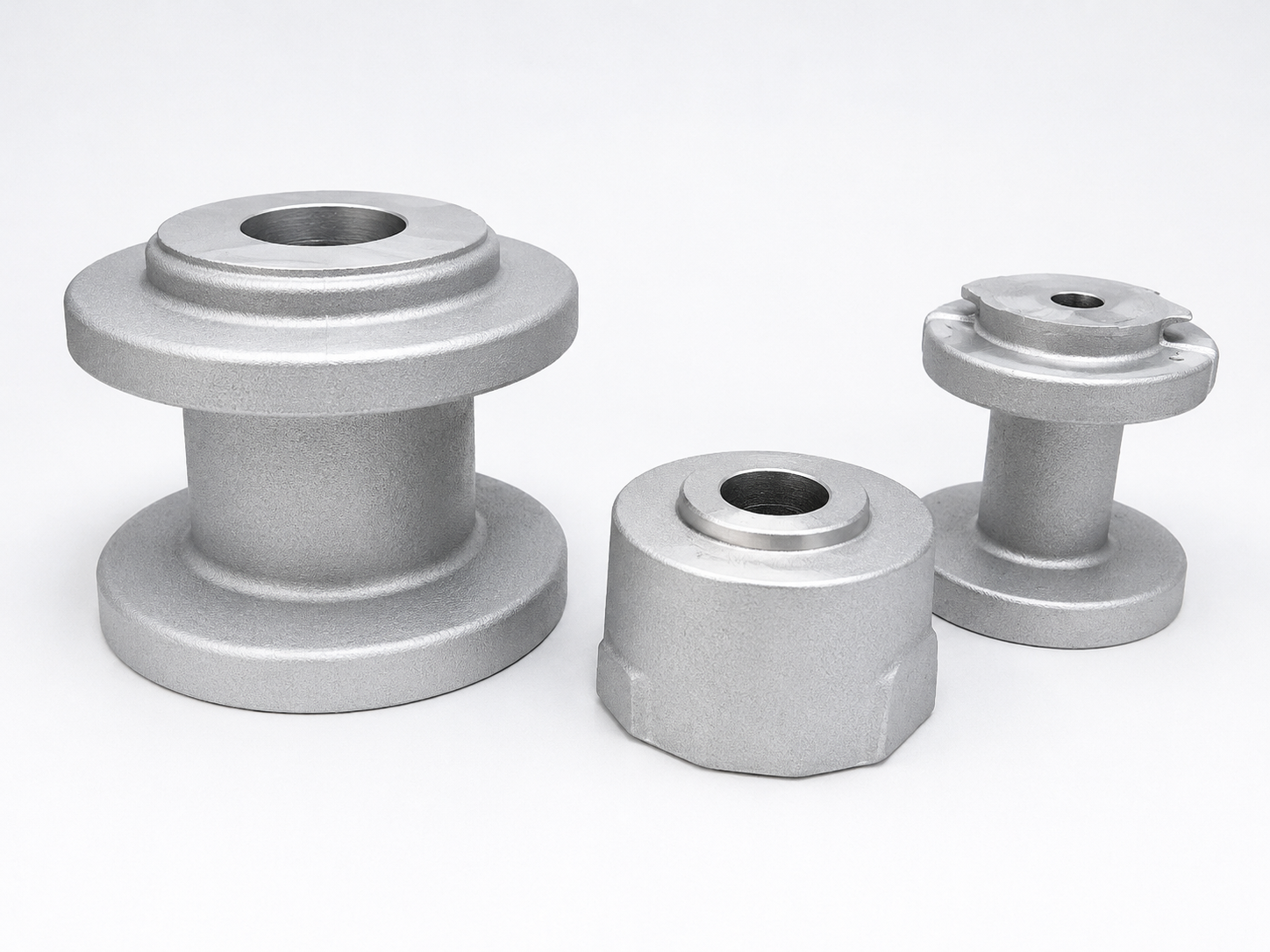 | Aluminium Gravity Die Castings An “oil engine spacer“ typically refers to an automotive or industrial component designed to resolve clearance issues, prevent oil starvation, or... View product → |
 | Aluminium Gravity Die Castings Spacers Spacers are physical objects or materials used to create space, maintain a specific distance, or separate components in various industries. |
Frequently asked questions
What should you identify before removing or reusing a spacer?
Determine whether it controls fixed shaft distance, bearing preload, endplay, gear or pump position, or crush-controlled clamp load.
How should you inspect a spacer before installation?
Clean every mating surface, then check the spacer and surrounding parts for burrs, cracks, fretting, corrosion, wear, and distortion.
Why must you recalculate the assembly stack?
The removed spacer’s length may not be correct. Recalculate the stack against the service specification to achieve the required distance, preload, endplay, position, or clamp load.
What should you record after reinstalling a spacer?
Record installation orientation, load sequence, measurements, test results, and the next inspection point.